


Click to view a full size picture (opens in a new tab)

On arrival the machine didn’t work. On power-on it just showed several digits over each other per digit position.
To assure a proper power supply I started with replacement of all its electrolytic capacitors. Next an in-circuit check of all diodes and transistors showed four defective diodes and one defective transistor. After replacement there was an improvement in the clear action after power-on.
It seems a bit odd to me that there are five defective components, while I would expect that a single defect would be enough to put the calculator aside.
After replacement of the defective components sometimes, but not always, a clear resulted in all-zero’s as expected. Trying to operate it, however, it often got stuck with fives like: 0 0000 0000 0000 5555
In the next phase technical documentation of the Canon 161 was helpful. There seems a lot of resemblance with the 130s. Also very helpful was the partial schematic for the Canon 130S, from Jean Campioni. (http://madrona.ca/e/eec/calctd/Canon130S/)
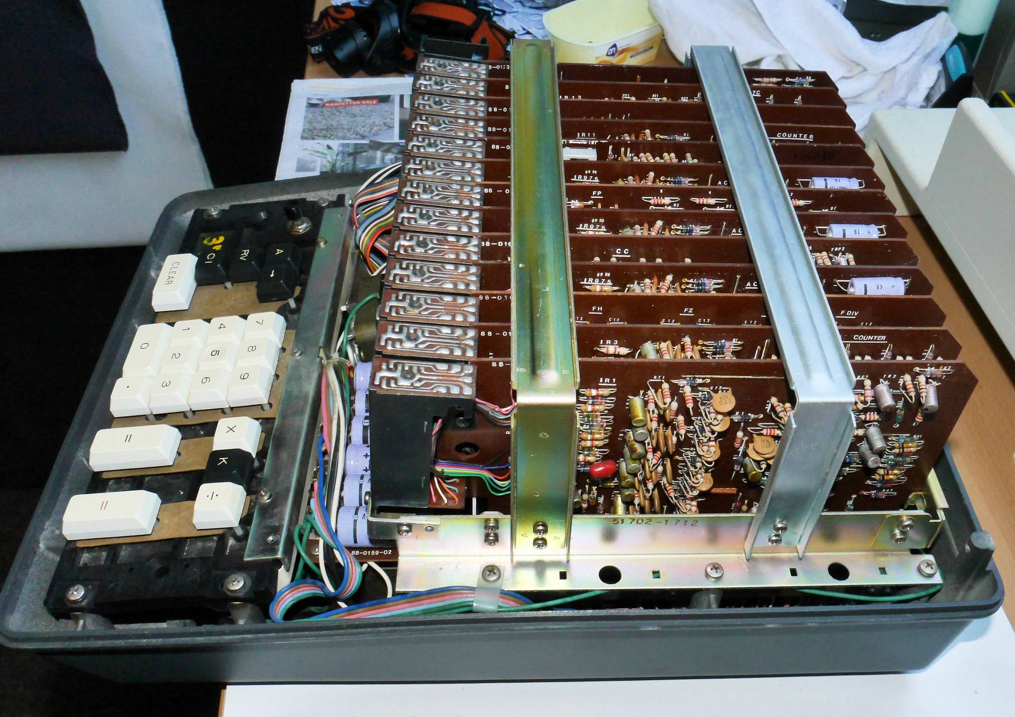
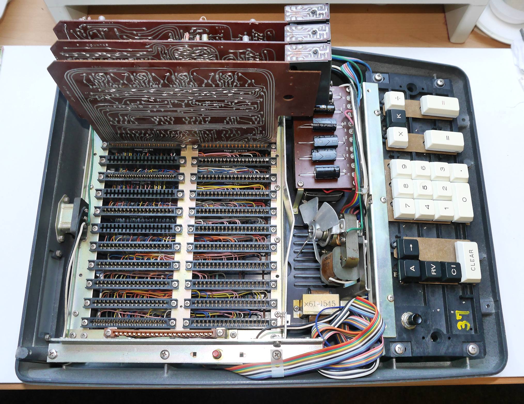
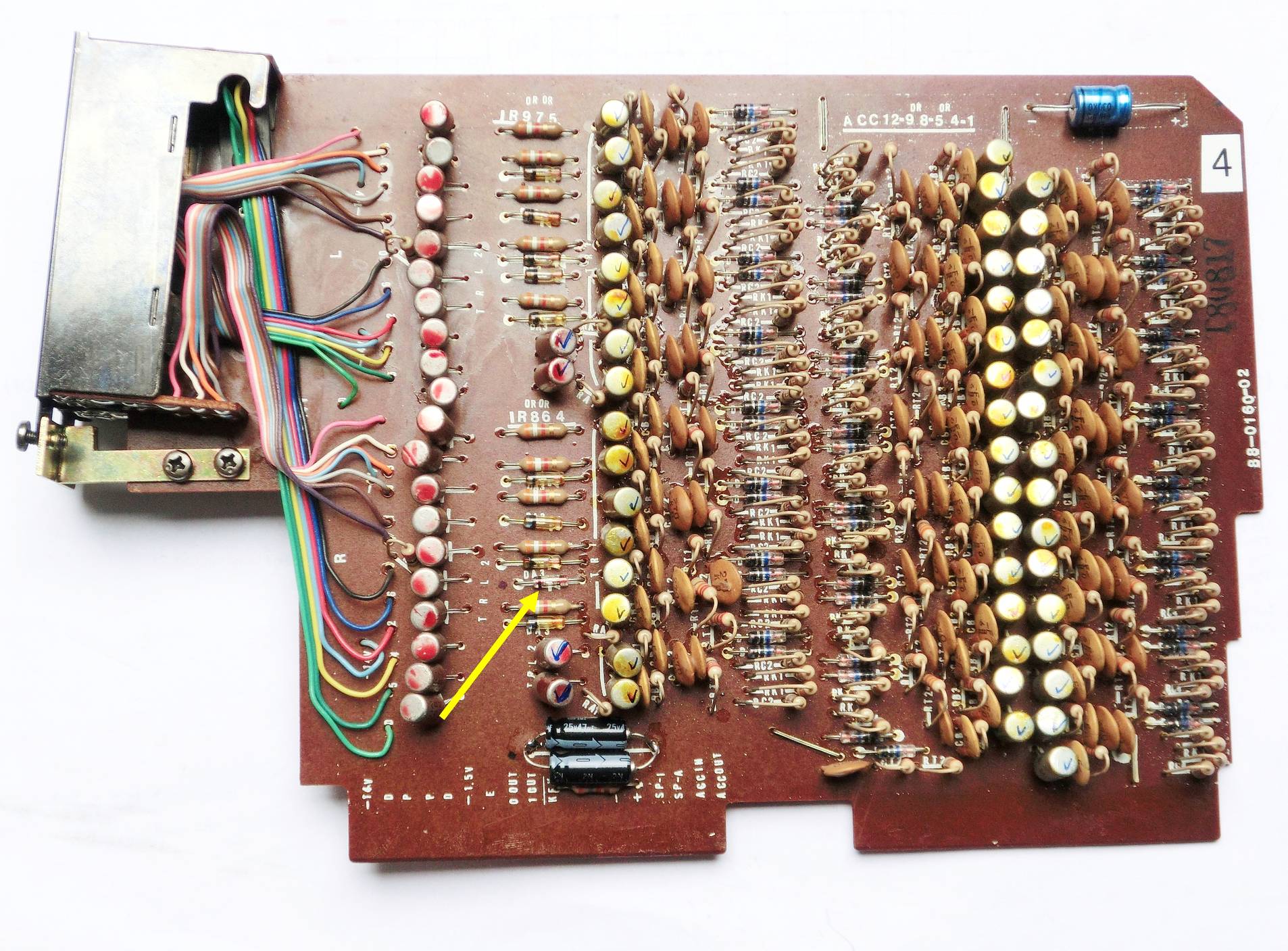
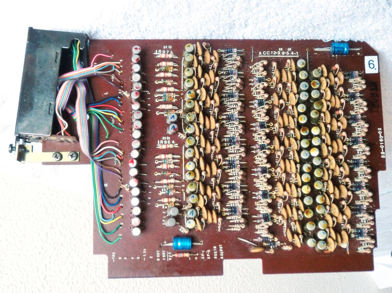
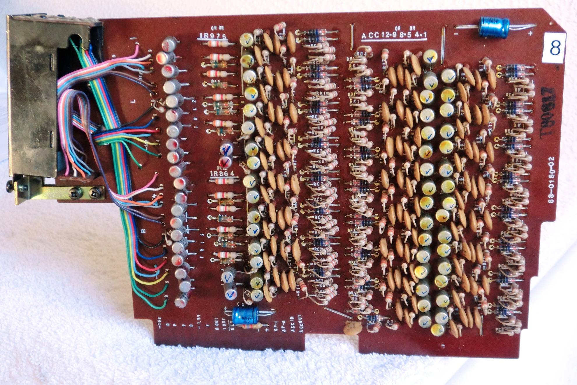
The calculator contains 13 printed circuit boards (counting 1 to 13 from right to left). Boards 4, 6 and 8 are identical. It appeared that swapping board 4 with 6 or 8 moved the “5-problem”. E.g. swapping 4 with 6 resulted in: 0 0000 0000 0055 5555. That made board 4 suspicious. Therefor I replaced all 2SA538 (germanium-PNP) transistors forming flip-flops by 2N3906 (silicium-PNP). Now a Clear often resulted in all zero’s. However, it didn’t calculate yet and still the display often showed 0 0000 0000 0000 5555.
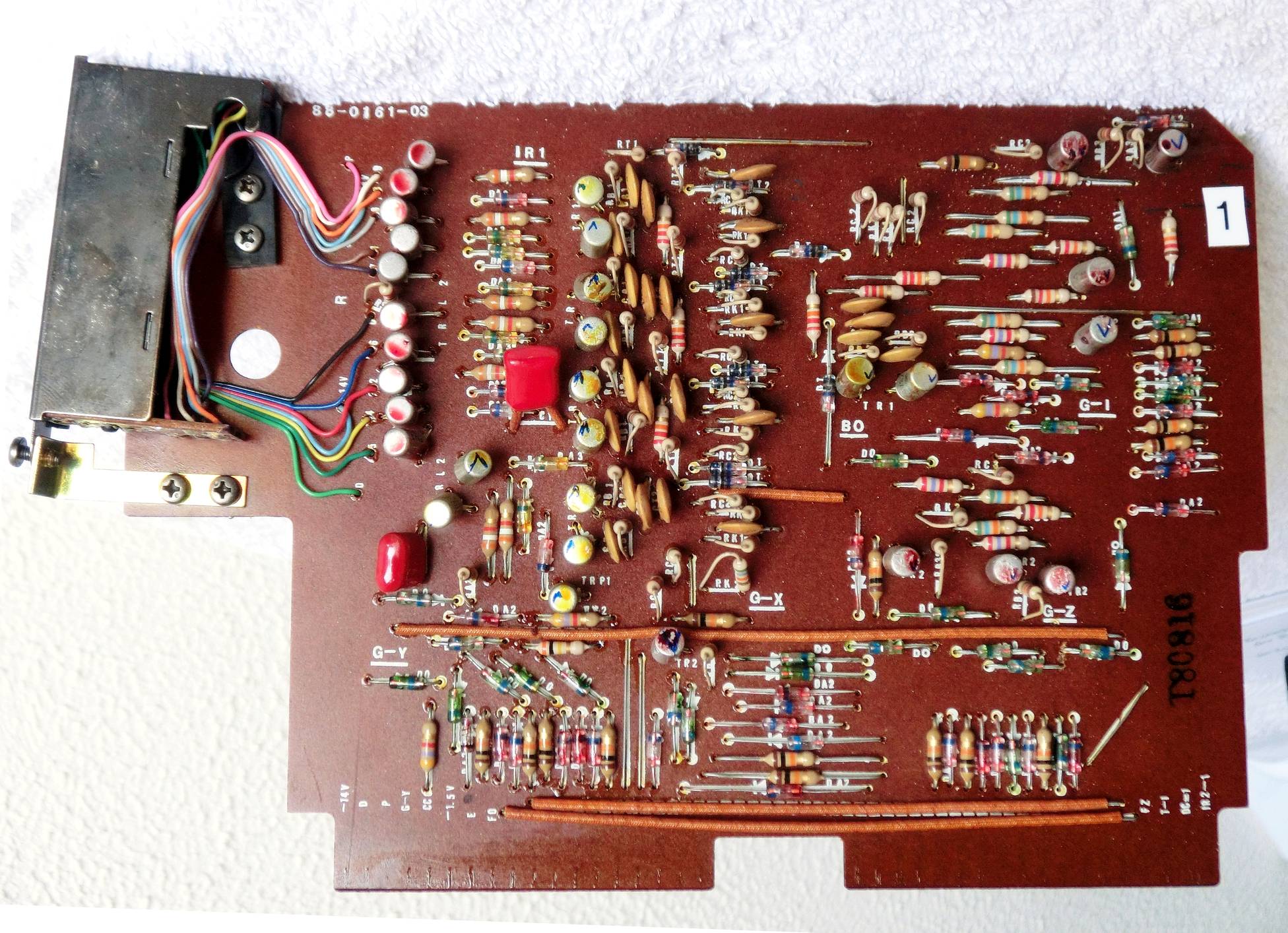
There was some reason to doubt proper functioning of board 1 (*). Therefor also on that board I replaced most of the flip-flop transistors.
Afterwards it was possible to do some calculations limited to digits 3, 6 and 9. At that point I left the calculator in this condition.
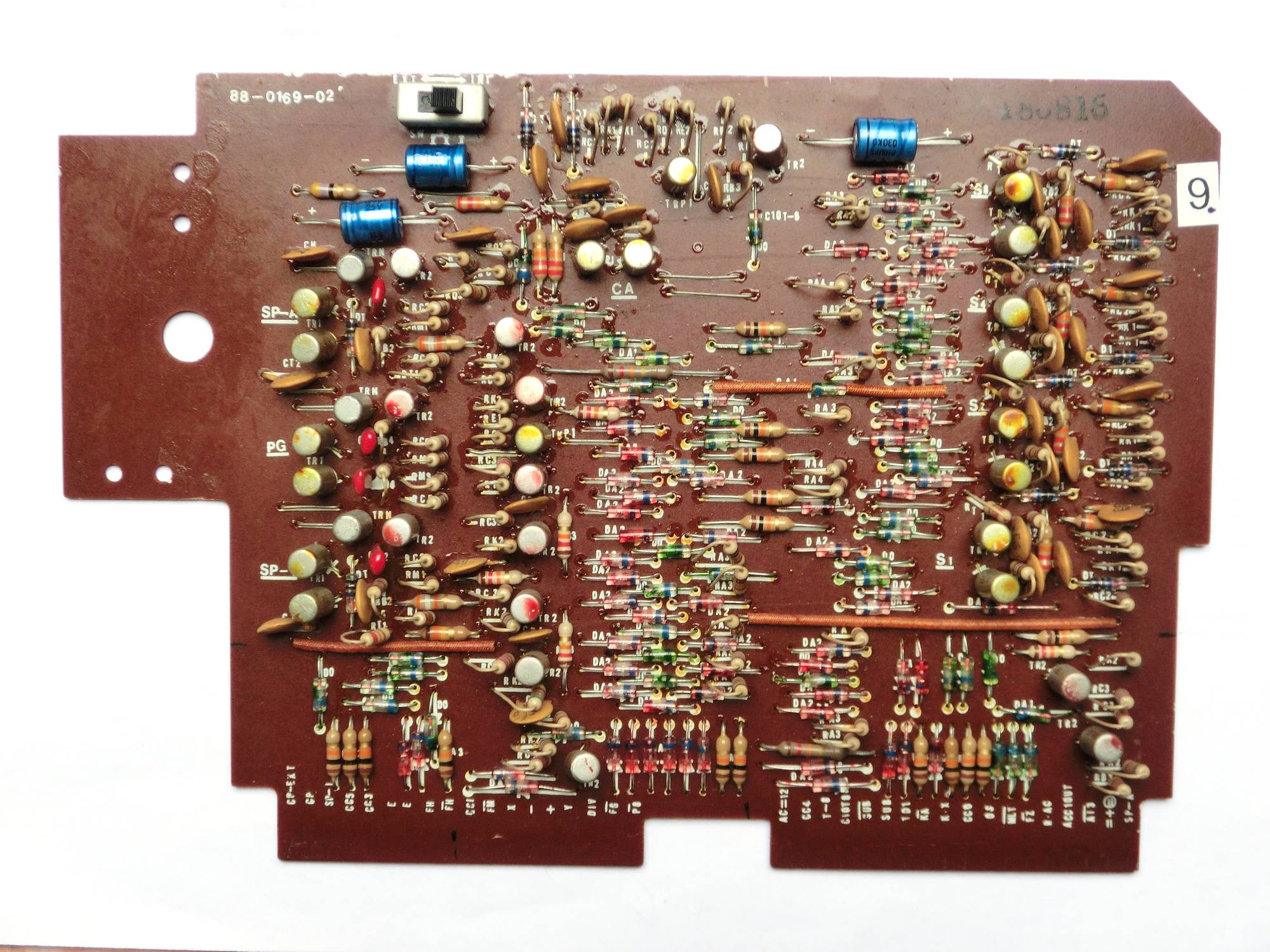
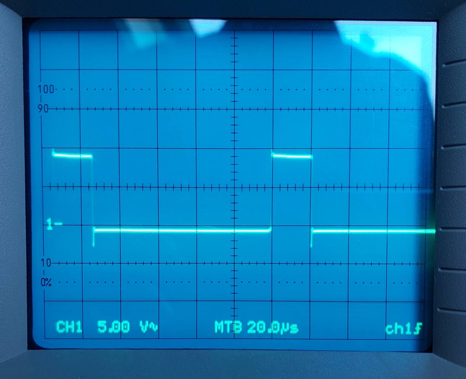
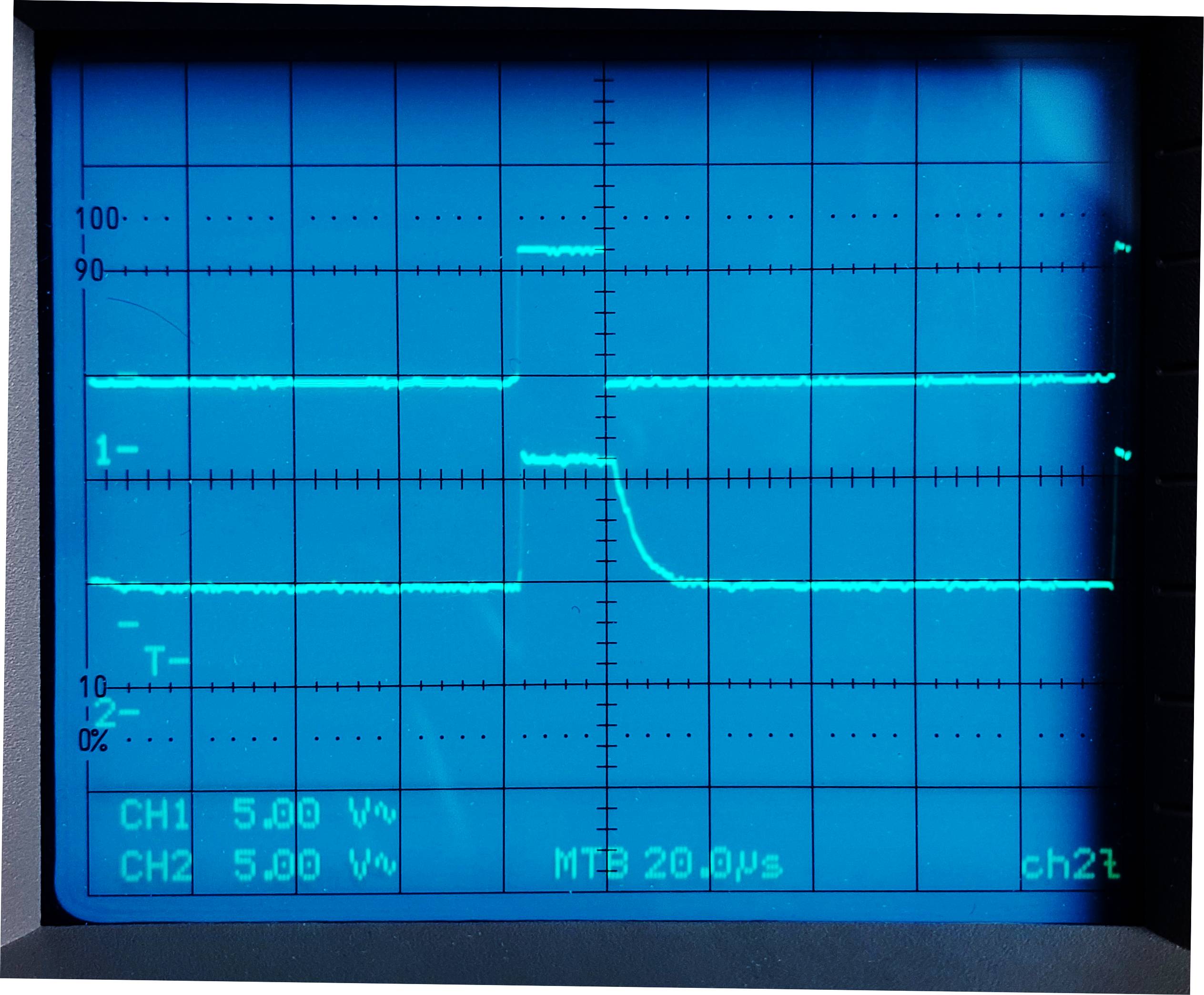
After a while I couldn’t resist another attempt to improve its operation. With help of digital scope I measured several signals, hoping to find one of suspicious quality. I found none! However, during these measurements I caused a short circuit in the push-pull output stage of the master clock on board 9. After mounting a new pair of replacing silicium transistors (2N3904/2N3906) the behaviour of the calculator improved significantly. The signal of the master clock now was clean i.e. missing the overshoot as seen in the pictures below. The calculator now functions perfectly!
(*) Note: None of the flip-flop transistors that I replaced was defective. The hFE, however ranged from 70 to 150. Maybe that this causes some flip-flops to switch less reliably?
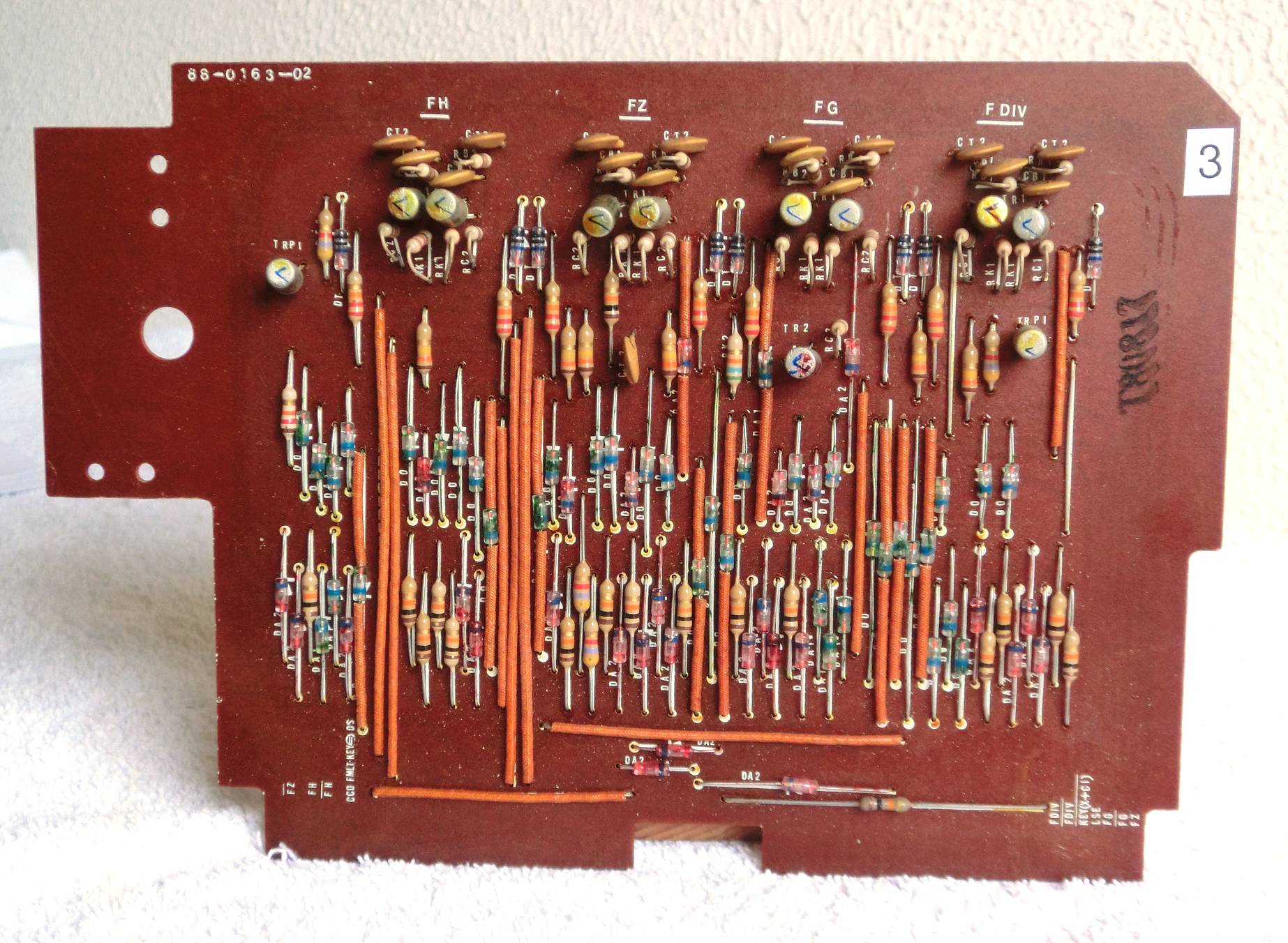
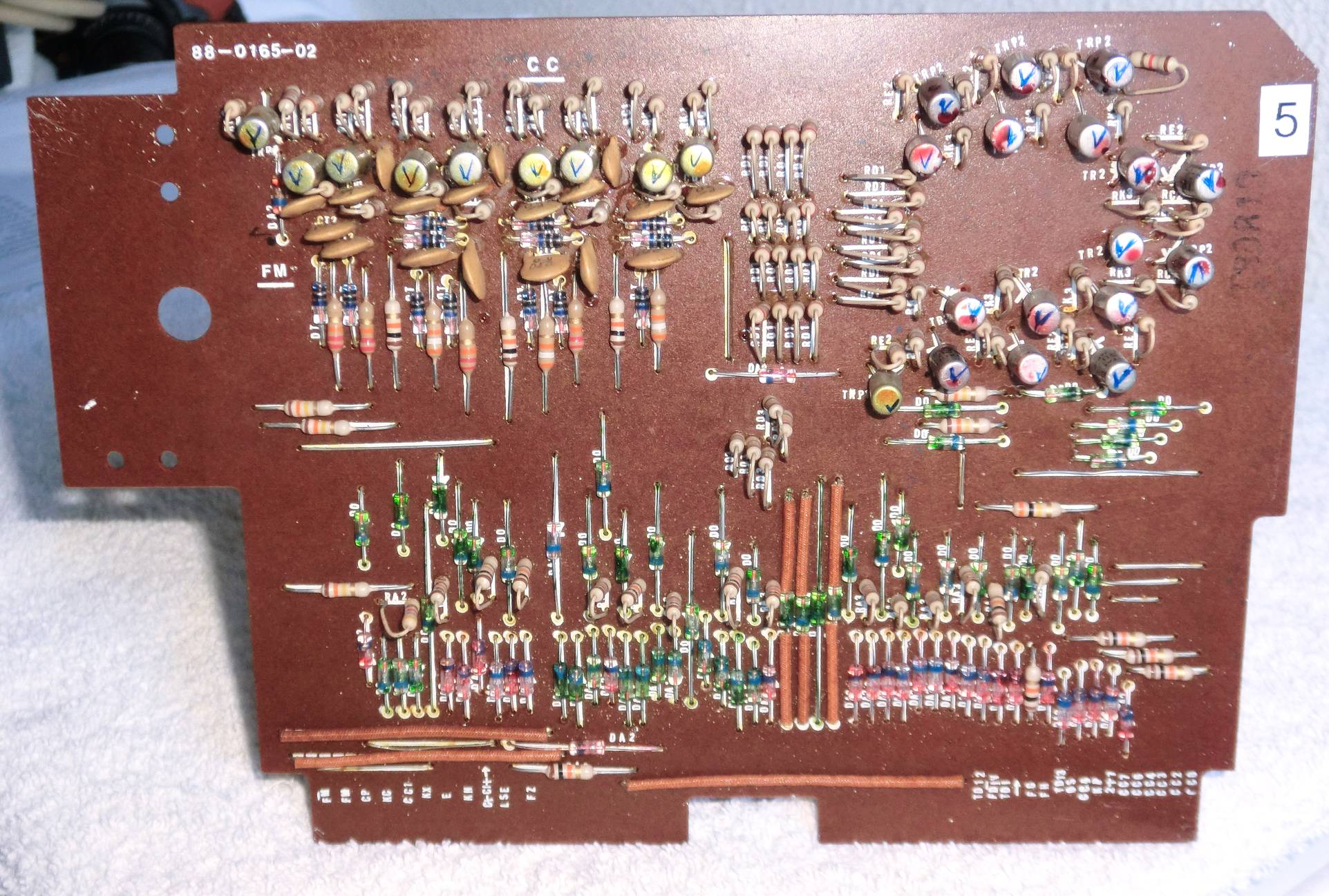
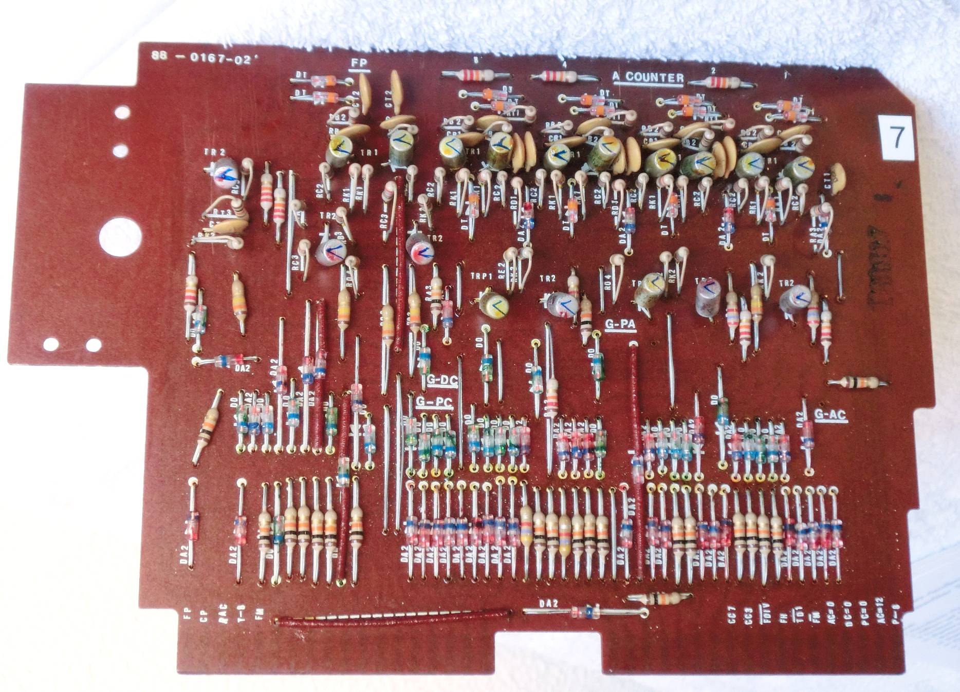
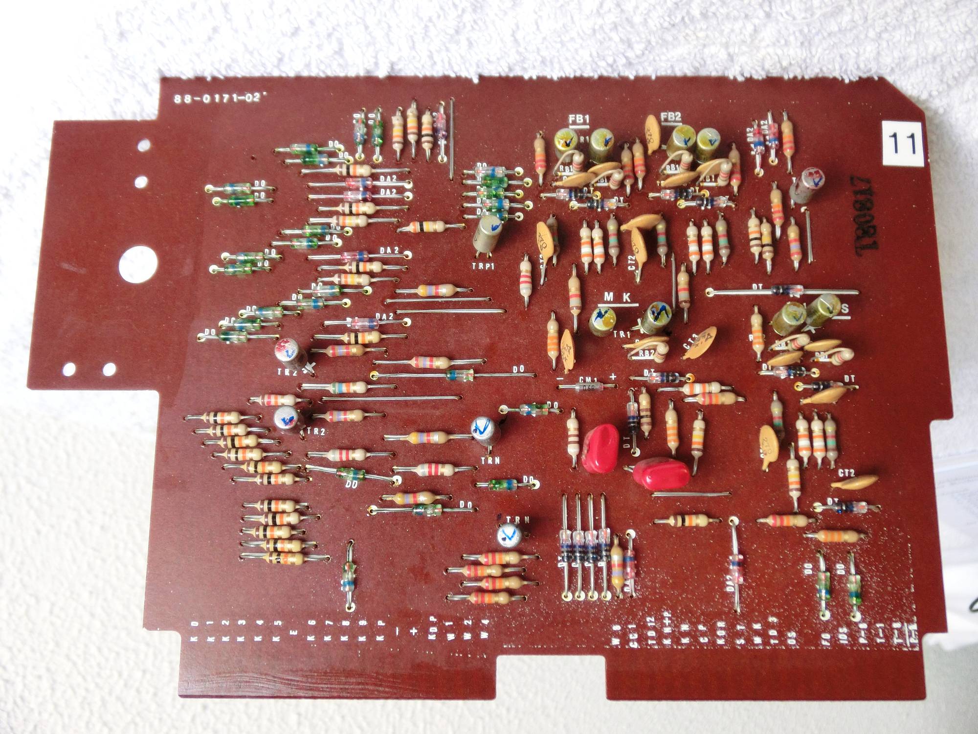
Below photo’s of the 13 PCB’s. They are numbered 1 to 13, where 1 is the right-most board (least significant digit position).
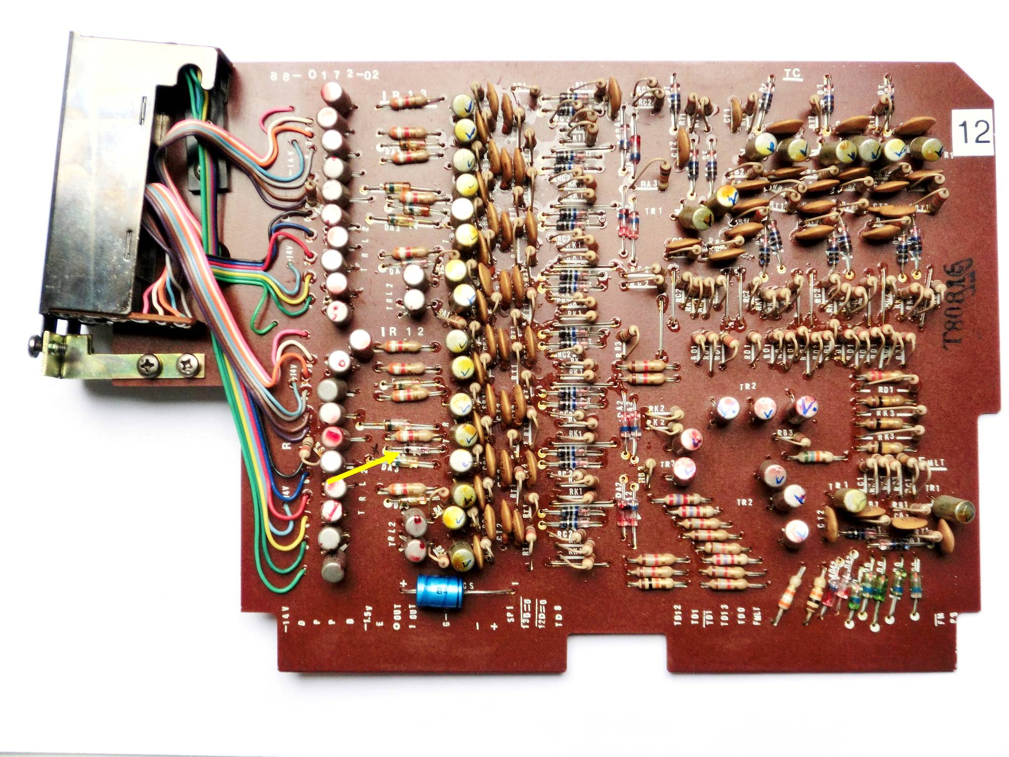
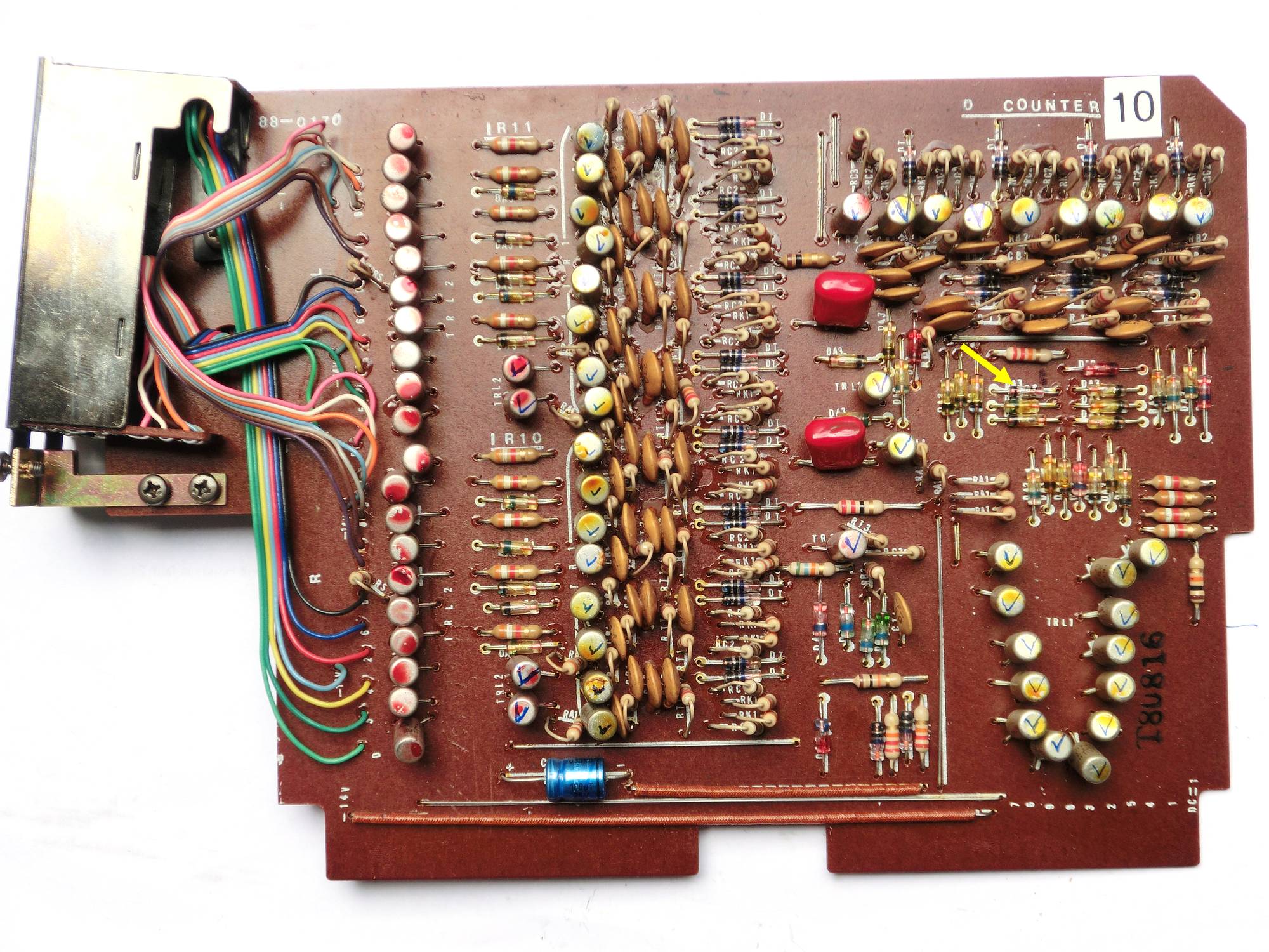
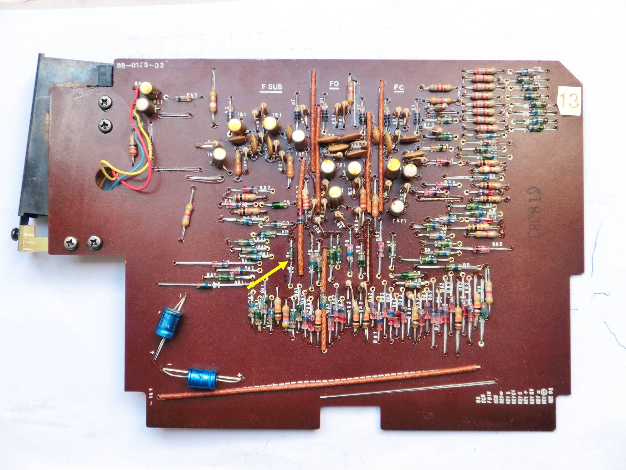
Defective diodes were found on boards 4, 10, 12 and 13. A yellow arrow points to those diodes.
On clicking a picture a full-size view opens in a new tab.


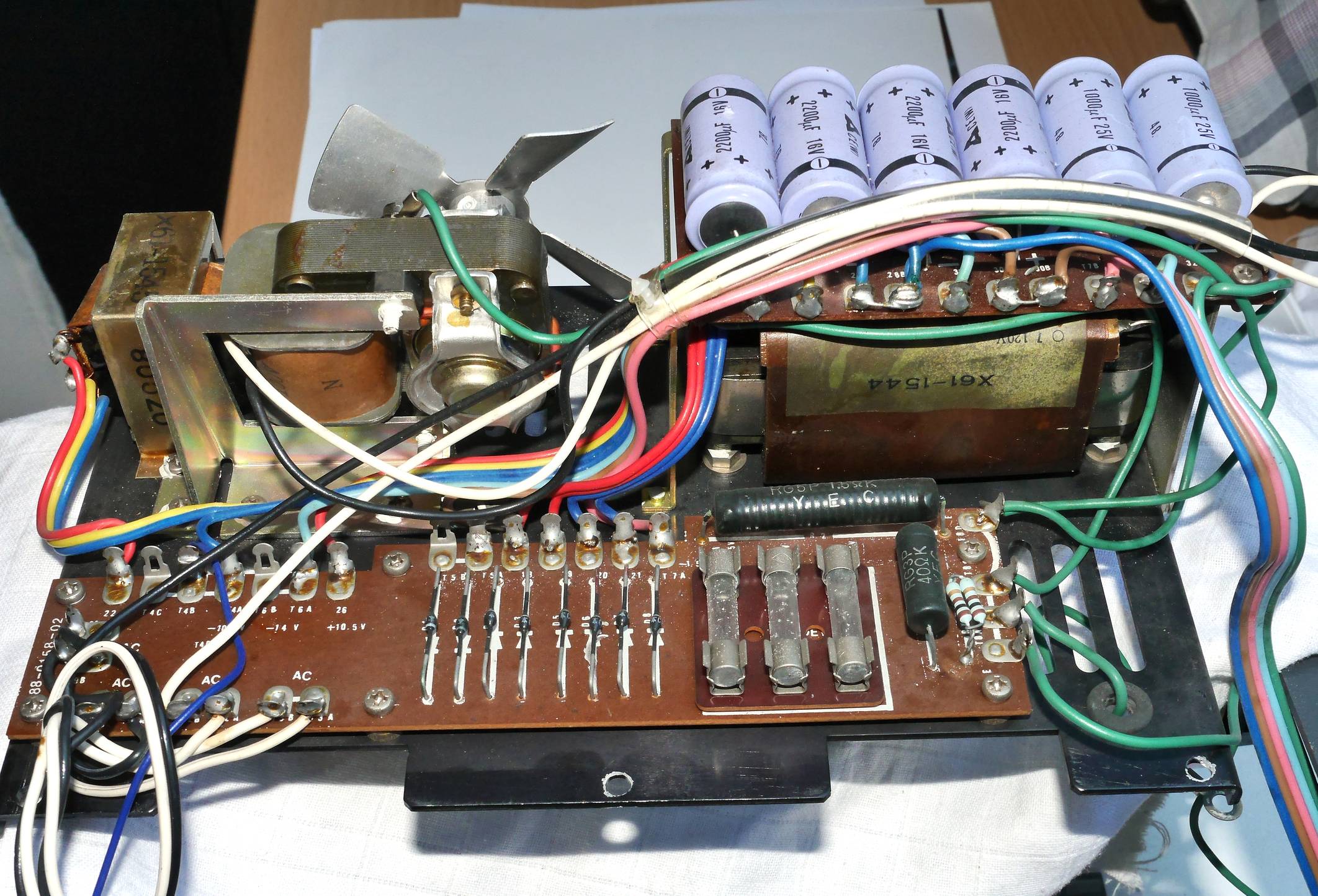
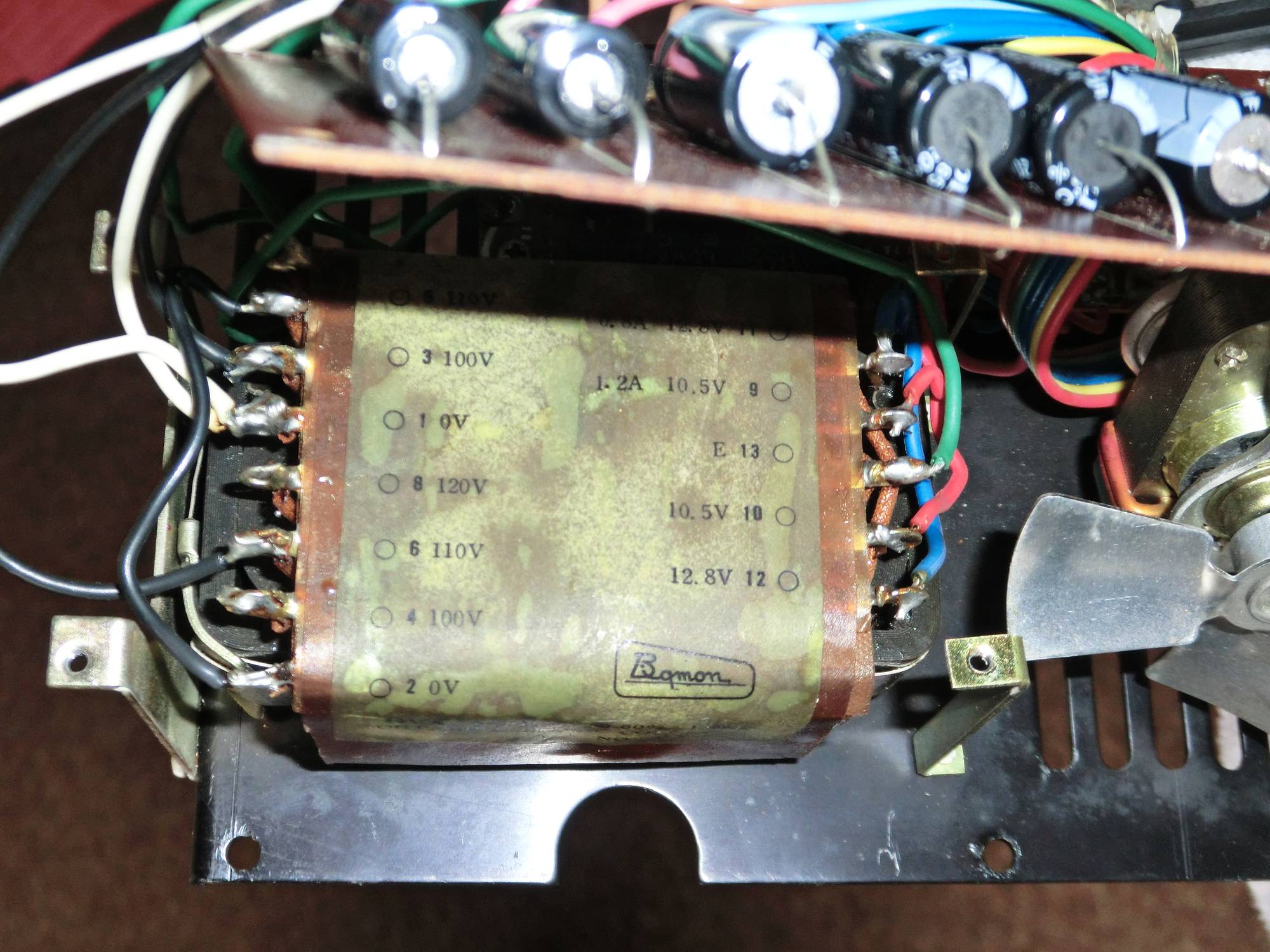
Original elco’s in the power supply
New elco’s in the power supply
PCB-1
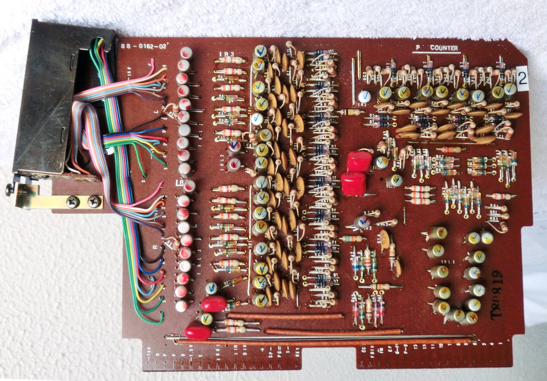
PCB-2
PCB-3
PCB-4
PCB-5
PCB-6
PCB-7
PCB-8
PCB-9
PCB-10
PCB-11
PCB-12
PCB-13
Master clock (Chan-1) on PCB9 after Si replacements (2N3906 / 2N3904)
Master clock on PCB9 with original Ge transistors (2SA538 / 2SD77)
| Mechanical Calculators |
| Electronic Calculators |
| Typewriters |