


Click to view a full size picture (opens in a new tab)

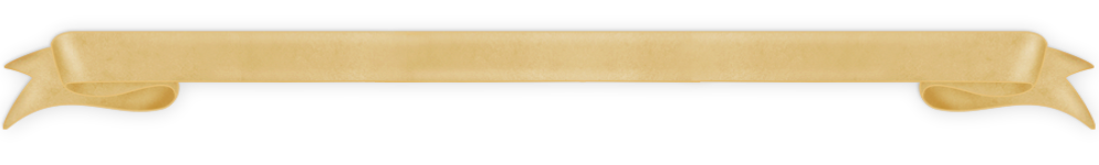
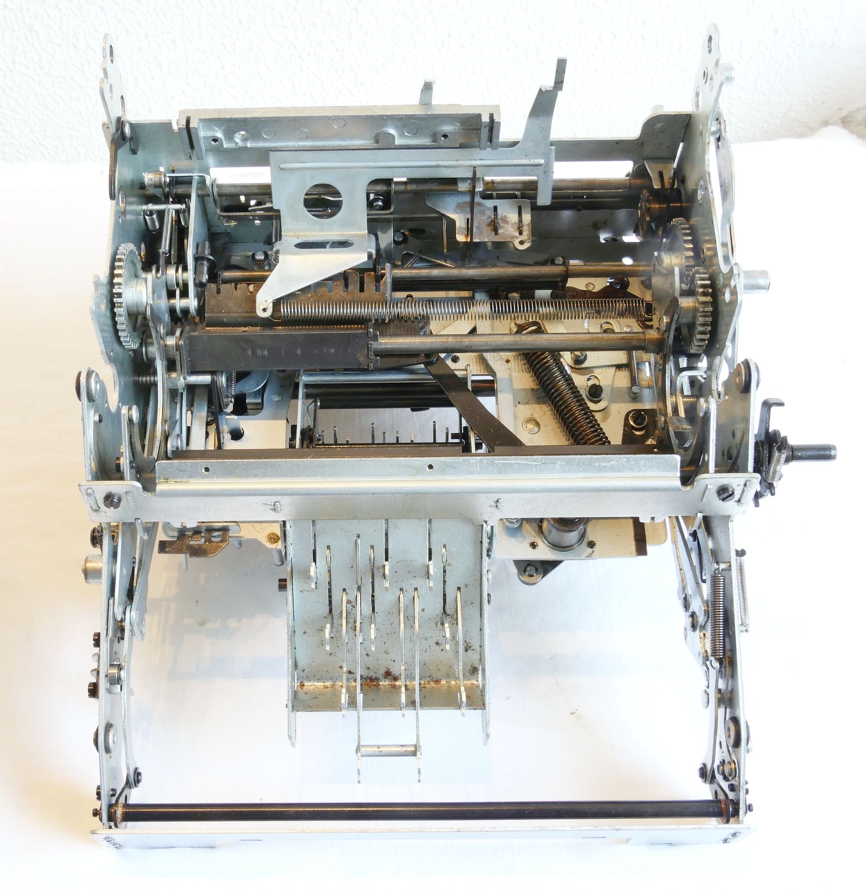
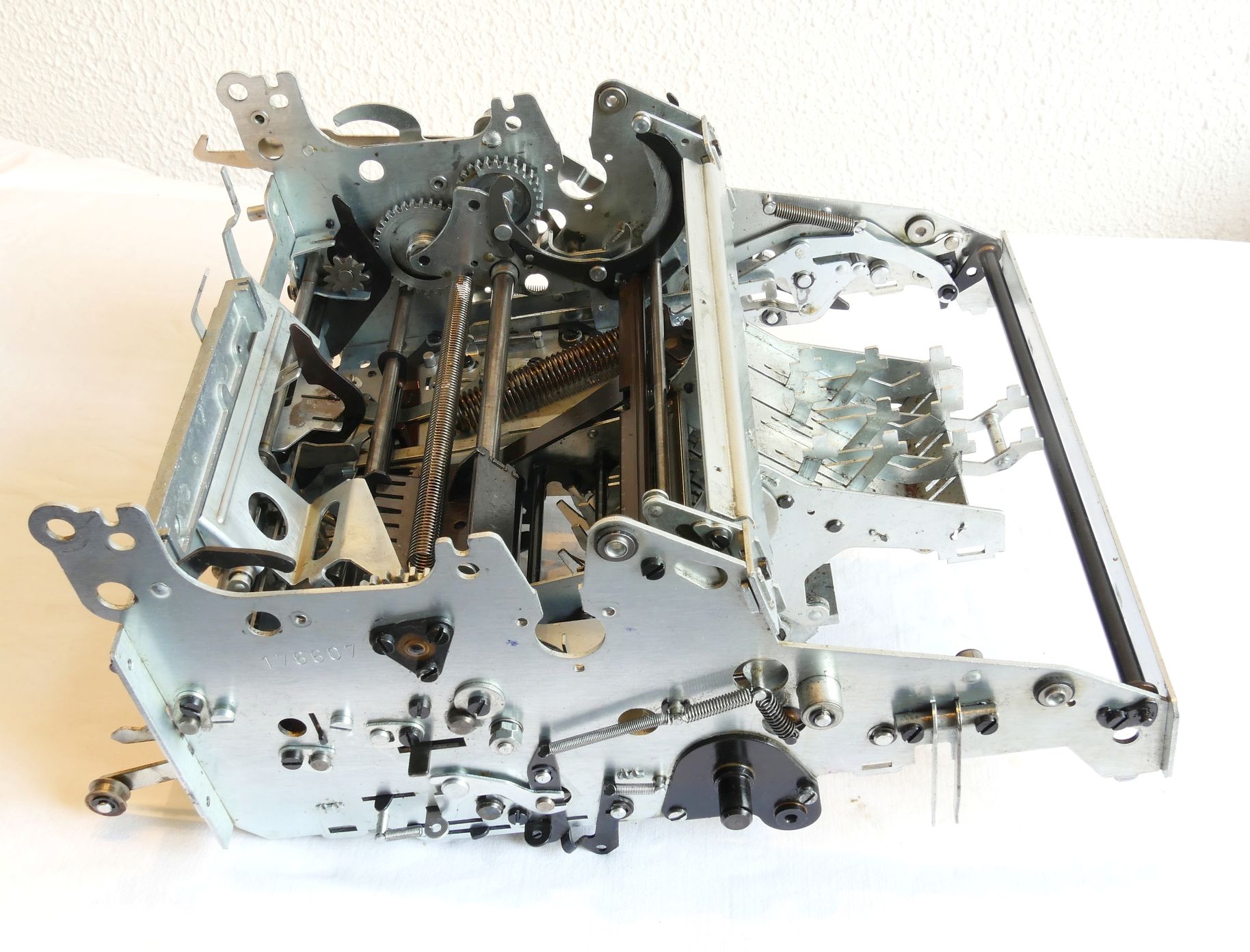
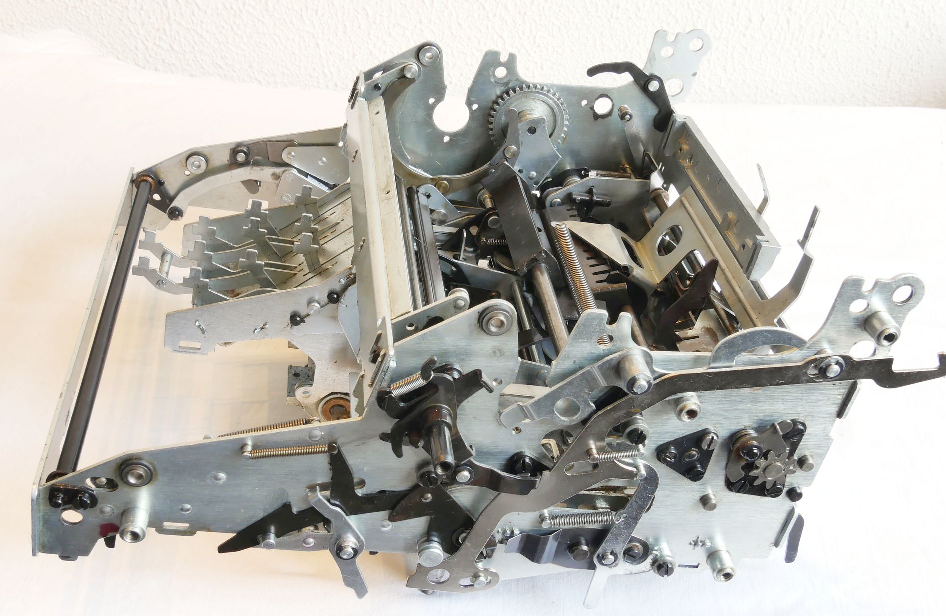
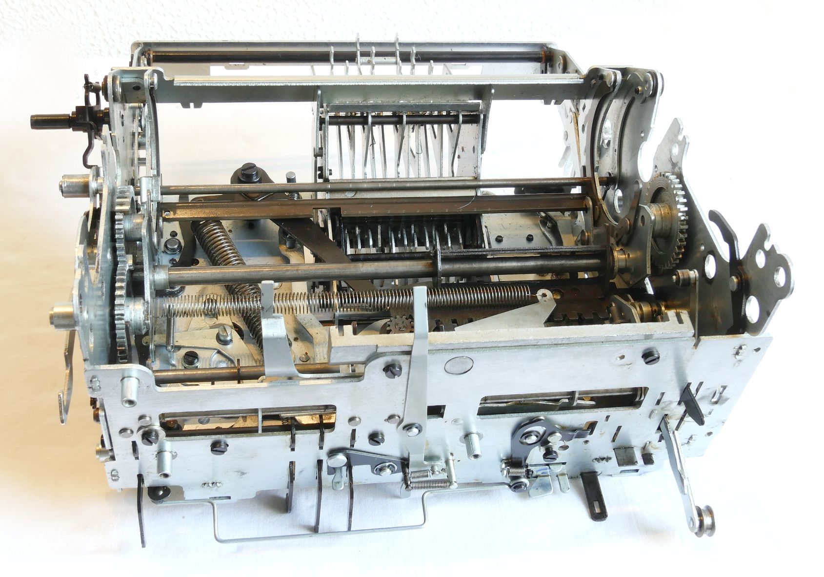
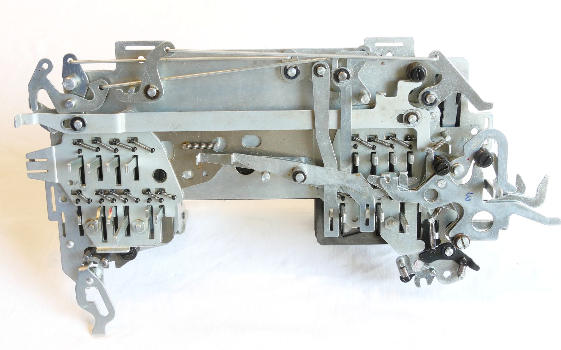
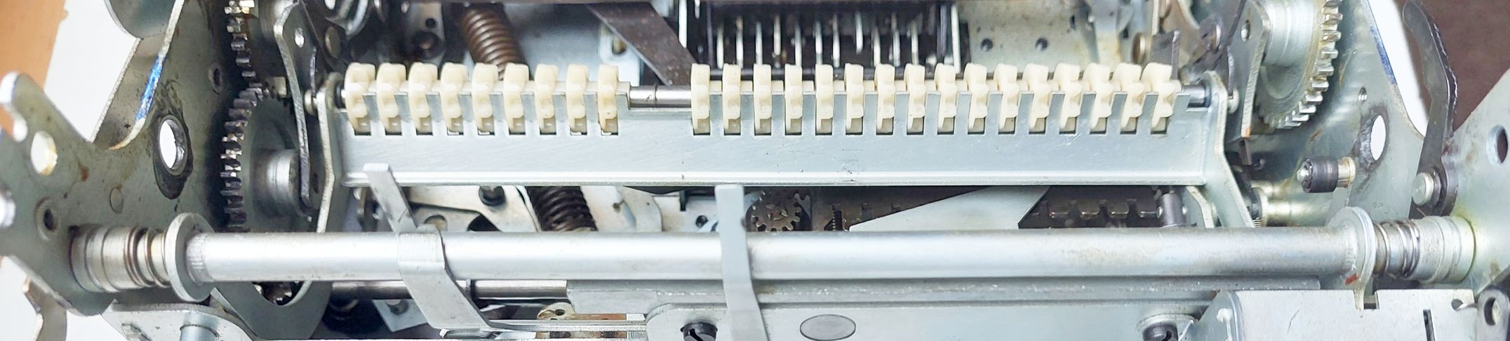
The internal construction of the machine consists of 10 modules connected to a Main Frame.
The modular construction allows for separate cleaning of the modules. For proper cleaning some parts needed to be removed from a module. In some cases a small gas torch (See: Repair Info) was necessary to loosen stuck parts.
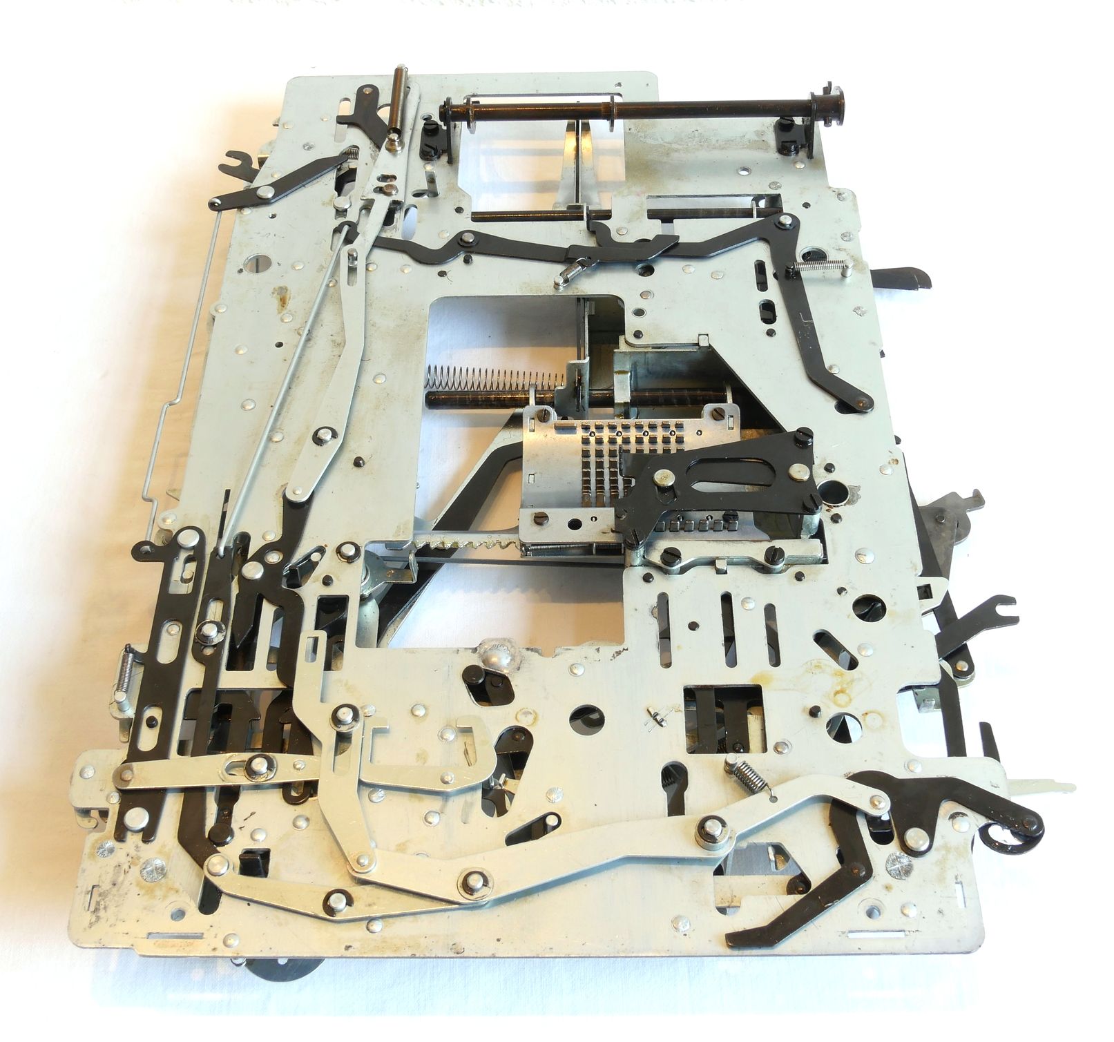
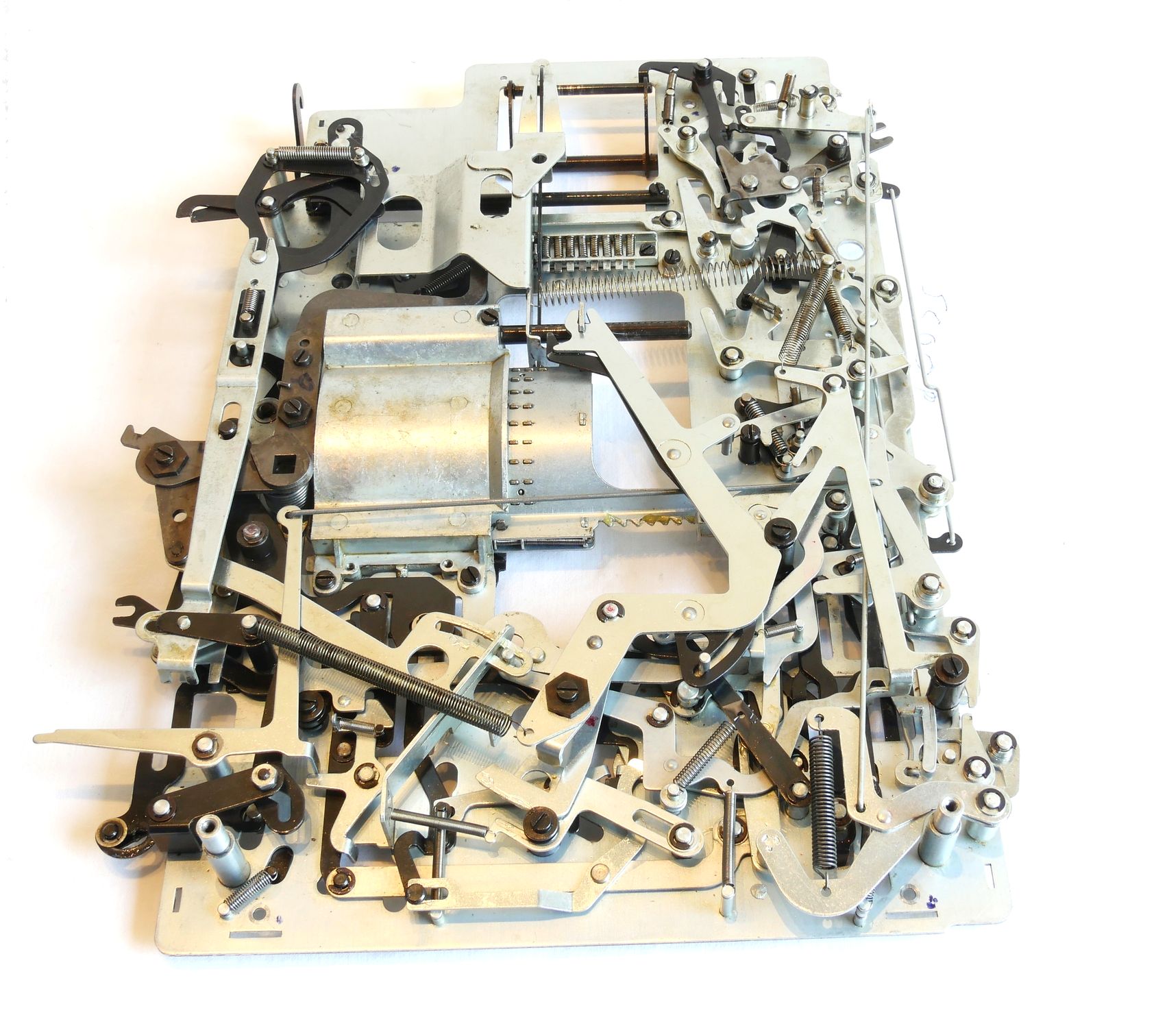
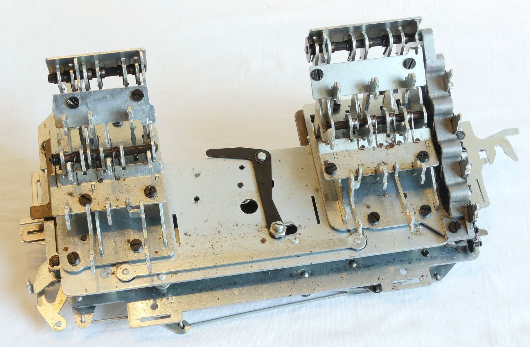
Most common are stuck control levers. For an example of a small part of the Bottom Sub-Assembly see the photo in the bottom corner of this page. Most of the control levers are located in Main Frame, Bottom Sub-Assembly and Back Corner Panel, often easily accessable, but unfortunately sometimes hidden behind other controls. Most controls are kept in place by an E-clip. Removal of the E-clip and taking of the control lever is necessary to remove all hardened grease. Often applying WD40 and allowing it to solve grease a bit helps to get some movement in parts. In some cases WD40 failed to loosen a part. In those cases I always managed to loosen a part by carefully applying local heat with a small gas torch.
Last but not least: I wouldn’t have managed to repair my machine without some documentation Google found on the internet:
- Facit-CA2-16 Restoration Manual.pdf
- Facit-CA2-16 Parts.pdf
Some youtube video’s may also be very helpful:
The Facit CA2-16 Calculator published by PeterBurton50 and
FACIT's fully automatic calculator CA2-16 in action published by Robert Hagström

s.jpg)
s.jpg)
)s.jpg)
s.jpg)
s.jpg)
s.jpg)
s.jpg)
s.jpg)
s.jpg)
—––––––––––––––––––– Main Frame –––––––––––––––––––––––-
Back Corner Panel
Bottom Sub-Assembly
Front Corner Panel & Function Keyboards
Registers II & III Sub-Assembly
Setting Rotor (Reg-I)
Tens Carry Rotors
Right-Hand Transmission Sub-Assembly
Back Transfer Sub-Assembly
Left Transmission Sub-Assembly
The Motor and its
Base Plate
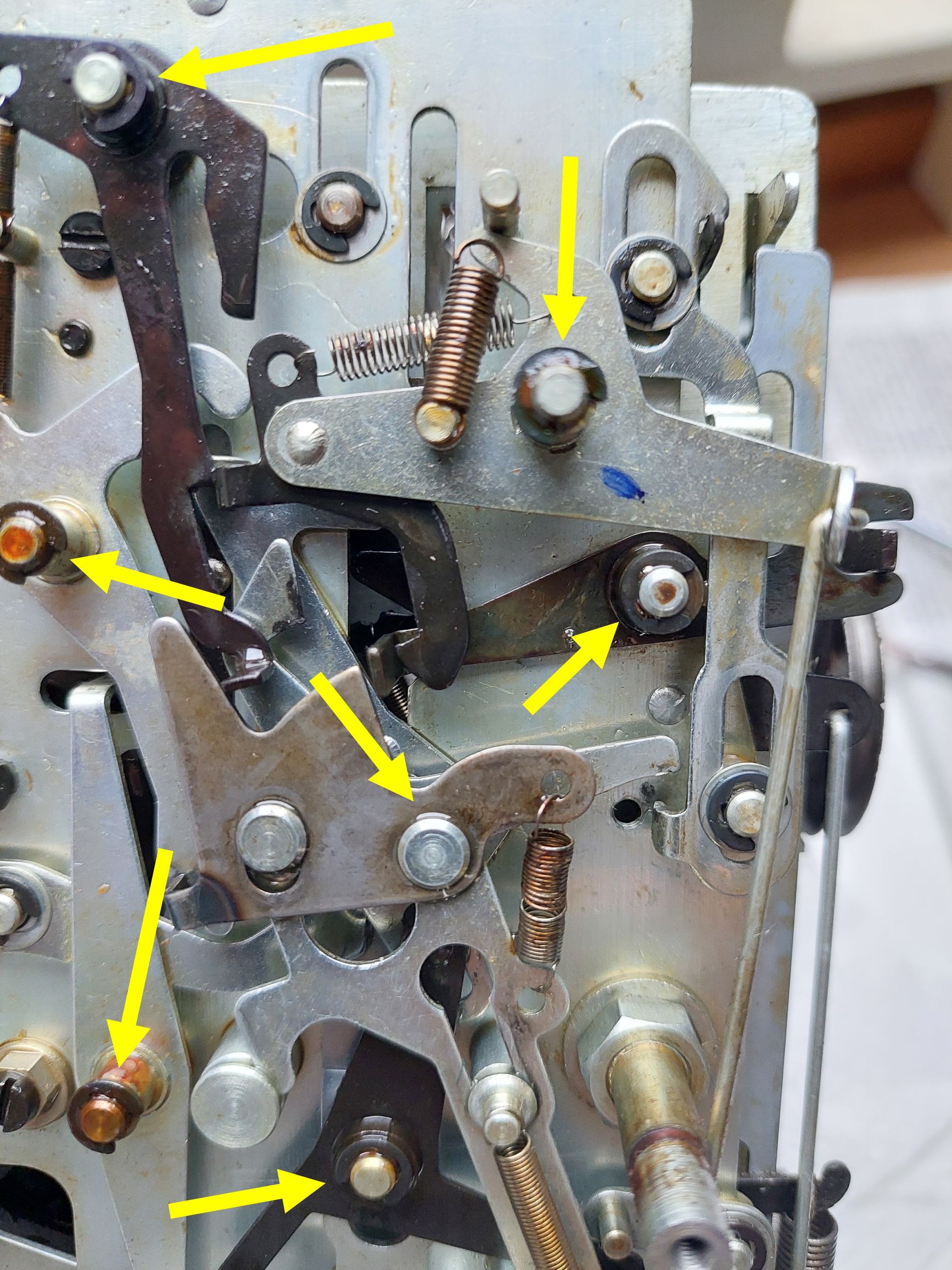
Blocked Levers
| Mechanical Calculators |
| Electronic Calculators |
| Typewriters |